Free papers at you mail box!

Want all latest paper presentations to improve your knowledge ?

Enter your email address here:

Search the topic your are looking for, save time!

Showing posts with label Embedded. Show all posts

VLSI - seminar

Students should be able to…
VLSI Circuit Analysis:
Understand MOS transistor operation, design eqns.
Understand parasitics & perform simple calculations
Understand static & dynamic CMOS logic
Estimate delay of CMOS gates, networks, & long wires
Estimate power consumption
Understand design and operation of latches & flip/flops
CMOS Processing and Layout 
Understand the VLSI manufacturing process. 
Have an appreciation of current trends in VLSI manufacturing.
Understand layout design rules. 
Design and analyze layouts for simple digital CMOS circuits
Design and analyze hierarchical circuit layouts. 
And more.. 


Asynchronous chip presentation

Paper presenation, free paper presentations, engineering paperpresention, paper presenation ideas, ECE paper presentation, EEE paper presentation, Mechanical Paper presenation, CS and IT Paper presentation.  ECE, EEE, MECH, IT, CSE, AERO, E&I and CIVIL.

Computer chips of today are synchronous. They contain a main clock, which controls the timing of the entire chips. There are problems, however, involved with these clocked designs that are common today. One problem is speed. A chip can only work as fast as its slowest component. Therefore, if one part of the chip is especially slow, the other parts of the chip are forced to sit idle. This wasted computed time is obviously detrimental to the speed of the chip.

    New problems with speeding up a clocked chip are just around the corner. Clock frequencies are getting so fast that signals can barely cross the chip in one clock cycle. When we get to the point where the clock cannot drive the entire chip, we’ll be forced to come up with a solution. One possible solution is a second clock, but this will incur overhead and power consumption, so this is a poor solution. It is also important to note that doubling the frequency of the clock does not double the chip speed, therefore blindly trying to increase chip speed by increasing frequency without considering other options is foolish.


Embedded system basics, paper presentation

paper presentation, engineering paper presentations, seminars, seminar topics, paper presentation topics, ECE, EEE, CSE, IT, MECH, AERO, AUTO, CHEM.


Embedded system

ABSTRACT:-
An embedded system can be defined as the computing device that has computer hardware, either with software embedded in it as one of its most important component. It may be an independent system or a part of a larger system. The emergence of embedded systems is a recent development. As a scientific discipline it resembles the state of microelectronics (and VLSI design, in particular) around 1980. Today’s challenge is similar to back then, except that the stakes are probably higher. Embedded systems will appear in virtually all devices, and intelligent devices have the tendency to oust their "stupid" counterparts from the market place, just like CD players have ousted gramophone players. Thanks to developments in microelectronics, the computing power of the desktop computers is now becoming available on the palmtops. Embedded systems are heterogeneous. Since they are mixtures of hardware and software, trade-off is important design decisions: do we realize a function in hardware or in software? But embedded systems are more heterogeneous than just combining computer science & digital electronics.
This paper presents an overview of existing modes of Embedded Systems, architecture & their application. A look has also been given to future deployment of Embedded Systems.


1. INTRODUCTION:-
An embedded system can be defined as the computing device that has computer hardware with software embedded in it as one of its most important component. It may be either an independent system or a part of a larger system. As its software usually embeds in ROM ,it does not need secondary memories as in a computer. Nearly 99% of the processors manufactured end up in embedded systems. Embedded systems find applications in every industrial segment. Embedded systems can be categorized as stand-alone systems, real-time systems, networked information appliances & mobile devices. Just in the 10 years, such changes have occurred more rapidly that they see more revolutionaries than evolutionary. As these systems have brought about radical changes in Electronics and Computer, they have also begun to impact other human activities.

INTRODUCTION TO EMBEDDED SYSTEM:-
An embedded system is some combination of computer hardware & software, either fixed in capability or programmable, that is specifically designed for a particular kind of application device. Hardware & software that forms a component of some larger system & is expected to function without human intervention. Typically an embedded system consists of a single-board microcomputer with software in ROM, which starts running a dedicated application as soon as power is turned on & does not stop until power is turned off. An embedded system is any device controlled by instructions stored on a chip. These devices are usually controlled by a microprocessor that executes the instructions stored on a Read Only Memory (ROM) chip. Here an example of a chip “PIC” is shown

An embedded system is pre-programmed to perform a dedicated or narrow range of functions as part of a larger system, usually with minimal end-user or operator intervention. The term 'embedded' implies that these chips are an integral part of the system. Broadly speaking, these programmable devices or systems are generally used to perform, control or monitor processes, machinery, environments, equipment and communications tasks.
Embedded systems have several things to do at once–respond to several
Events at once; cope with unusual conditions without human intervention, while being subjected to a deadline. In fact a general computer system is made up of numerous embedded systems. If an embedded system is designed well, the existence of the processor & the software could be completely unnoticed by a user of the device.


2. CATEGORIES OF EMBEDDED SYSTEM:-

2.1 Stand-alone Embedded Systems:-
As the name implies, stand-alone systems work in stand-alone mode. They take inputs, process them & produce the desired output. The input can be electrical signal from transducers or commands from a human being such as pressing of a button. The output can be electrical signals to drive another system, an LED or LCD display for displaying of information to the users. Embedded Systems used in process control,automobiles,consumer electronic items etc. fall into this category in a process control system, the inputs are from sensors that convert a physical entity such as temperature or pressure into its equivalent electrical signal. These electrical signals are processed by the system and the appropriate electrical signals are produced.

2.2. Real-time Systems:-
Embedded Systems in which some specific work has to be done in specific time period are called real-time systems. For example- Consider a system that has to open a valve within 30 milliseconds when the humidity crosses a particular threshold. If the valve is not opened within 30 milliseconds, a catastrophe may occur. Such systems with strict deadline are called hard real-time systems. On the other hand, if we consider a DVD player and we give some command from a remote control, & there is a delay of a milliseconds in executing the command, but this delay won’t lead to a serious implication. Such systems are called as soft real-time systems.

2.3 Network Information Appliances:-
Embedded systems that are provided with network interfaces & accessed by networks such as Local Area Network or the Internet are called networked information appliances. Such embedded systems are connected to a network, typically a network running TCP/IP (Transmission Control Protocol/Internet protocol) protocol suite, such as the Internet or the Company’s Intranet. These systems have emerged in recent years.
Here are some examples of such systems:-
A networked process control system consists of a number of embedded systems connected as a LAN. Each embedded system can send real-time data to a central location from where entire process control system can be monitored. The monitoring can be done using a web browser such as the Internet Explorer.
The door-lock of your home can be a small-embedded system with TCP/IP and HTTP server software running on it. When your children stand in front of the door-lock after they return from school, the web camera in the door-lock will send an alert to your desktop over the Internet and then you can open the door-lock just by clicking the mouse.


3.OVERVIEW OF EMBEDDED SYSTEM ARCHITECTURE:-
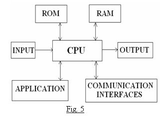
Every embedded system consists of custom – built hardware built around a Central Processing Unit (CPU). This hardware also contains memory chips onto which software is loaded. The software residing on the memory chip is called the firmware. The embedded system architecture can be represented as a layered architecture as shown in fig-4. The operating system runs above the hardware and the application software run above the operating system. It is not compulsory to have an operating system in every embedded system. For small appliances such as remote control units, air conditioner, toys etc., there is no need for an operating system. For applications involving complex processing, it is advisable to have an operating system. In such a case, you need to integrate the application software with the operating system & then transfer entire software into a memory chip. Once the software is transferred to the memory chip, the software will continue to run for a long time & you don’t need to reload the new software.


3.1 Building Block of hardware of an Embedded System:-
Central Processing Unit (CPU):-
The CPU is a unit that centrally fetches
& processes a set of general-purpose instructions. The CPU instruction set includes instructions for data transfer operations, ALU operations, stack operations, input &output operations & program control, sequencing & supervising operations. The general-purpose instruction set is always specific to a specific CPU. One example of an older generation Microprocessor is Intel 8085.It is an 8-bit processor. Another is Intel 8086 or 8088, which is a 16-bit processor.

The CPU can be of the following:-
Microcontroller, microprocessor or Digital Signal Processor (DSP).
A micro-controller is a low-cost processor. Its main attraction is that on the chip itself, there will be many other components such as memory, ADC
etc. on the other hand, microprocessors are more powerful, but you need to use many external computers with them. DSP is mainly used for applications in which signal processing is involved.

Processor in the System:-
An embedded system processor chip or Core can be one of the following.

1. General Purpose Processor (GPP):-
a) Microprocessor
b) Microcontroller
c) Embedded processor
d) Digital signals processor (DSP)
e) Media Processor

2. Application Specific System Processor
(ASSP) As Additional Processor

3. Multiprocessor system using General
Purpose processors (GPPS) & Application Specific Instruction Processors (ASIPs)

4. GPP core(s) or ASIP core (s) integrated into either an Application Specific Integrated Circuit
Circuit (ASIC) or a Very Large Scale
Integrated Circuit (VLSI) circuit or an FPGA core integrated with processor unit(s) in a VLSI (ASIC) chip.

Block diagram of Component of the Embedded System Hardware:-


Processor:-
A processor is the heart of the embedded system. For an embedded system designer, knowledge of microprocessors & Microcontrollers is a prerequisite. A processor has two essential units:

1. Program flow Control Unit (CU)
2. Execution Unit (EU)

The CU includes a fetch unit for fetching instruction from the memory. The EU has circuits that implement the instructions pertaining to data transfer operation & data conversion from one form to another. The EU includes the Arithmetic and Logical Unit (ALU)
& also the circuits that execute instructions for a program control tasks, say, halt, interrupt, or jump to another set of instructions. It can also execute instructions for a call or branch to another program & for a call to a function. Processors runs the cycle of fetch & execute the instruction defined in the processor instruction set are executing in the sequence that they are fetched from the memory. A processor
is mostly in the form of an IC chip; alternatively it could be in core form in an ASIC or at a Soc. Core means a part of the functional circuit on the VLSI chip.

A General Purpose Processor is used because of the following:-

1) Processing by the known instructions
Available at redefined general-purpose instruction set result in fast system development.
2) Once the board & input/output interfaces are designed for a GPP, these
Can be used for a new system by just changing the embedded software in the
Board ROM.
3) Ready availability of a compiler
Facilitates embedded software development in high level language.
4) Ready availability of a well tested &
Debugged processor specific APIs & the
Codes previously designed for other
Applications results in fast development
of new system.

Microprocessor:-
A microprocessor is a single VLSI chip
that has a CPU &may also have some other units (for eg: floating-point processing arithmetic unit, pipelining &super-scaling units) that are additionally present & that result in faster processing of instructions.

Memory:-
The memory is categorized as Random Access Memory (RAM) and Read Only Memory (ROM). The contents of RAM will be erased if power is switched off. So, the firmware is stored in the ROM. When the power is switched on, the CPU reads the ROM, the program is transferred to RAM and program is executed.

Input devices:-
Unlike the desktops, the I/P devices to an embedded system have very limited capability. There will be keyboard or a mouse, & hence interacting with the embedded system is no easy task. Many embedded systems will have a small keypad-you press one key to give a specific command. A keypad may be used to I/P only the digits. Many embedded system uses in process control do not have any I/P device for user interaction; they take I/Ps from sensors or transducers & produce electrical signals.

Output devices:-
The output devices of the embedded systems also have very limited capability. Some embedded systems will have a few Light Emitting Diodes to indicate the health status of the system modules. A small Liquid Crystal Display
(LCD)may also be used to display some important parameters.

Communication interfaces:-
The embedded systems may need to interact with other embedded systems or they may have to transmit data to a desktop.

Application-specific circuitry:-
Sensors, transducers, special processing & control circuitry may be required for an embedded system, depending on its application. The circuitry interacts with the processor to carry out the necessary work.


4. SPECIALITIES OF EMBEDDED SYSTEMS:-
While designing the embedded systems, developers have to keep the below specialties in mind: -

4.1 Performance:-
Many embedded systems have time constraints. For instance, in a process control system, a constraint can be: “if the temperature exceeds 40 degrees, open a valve within 10 milliseconds.” The system meets such deadlines. If the deadlines are missed, it may result in a catastrophe. You can imagine the damage that can be done if such deadlines are not met in a safety system of a nuclear plant.

4.2 Power Consumption:-
Most of the embedded systems operate through a battery. To reduce the battery drain & avoid frequent recharging of the battery, the power consumption of an embedded system has to be very low.

4.3 Cost:-
For an embedded system used in safety applications of a nuclear plant or in a spacecraft, cost may not be a very important factor. However, for an embedded system used in consumer electronics or office automation, the cost is of utmost importance. Suppose you have designed a toy in which the electronics will cost US$20. By a careful analysis design, if you can telecom operator will change the algorithm for the calculation of the bill amount. This is very cumbersome, considering that a memory chip will have to replace in thousands of PCO.

4.4 Size:-
Size is certainly a factor for many embedded systems. We do not like a mobile phone that has to be carried on our backs. The size and the weight
(ie.compactness) are the important parameters in embedded systems used in aircraft, missiles etc. because in such cases, every inch & every grain matters.

4.5 Software Up gradation capability:-
Embedded systems are meant for a very specific task. So, once the software is transferred to the embedded system, the same software will run throughout its life. However, in some cases, it may be necessary its upgrade the software. Consider the example of a Public Call Office (PCO). At the PCO, an embedded system is used which displays the amount to be paid by a telephone user. The amount is calculated by a firmware, based on the calling number & the duration of the call from time to time, the broadband & wireless network, & consumer electronic products.


5. RECENT TRENDS IN EMBEDDED SYSTEMS:-
In old good days, developing embedded systems was confined to very specialists. Most of the embedded systems are written only in assembly language & hence writing, debugging & maintaining the code were very difficult & time consuming. With the availability of powerful processors & advanced development tools, embedded software development is no longer ‘rocket science’.
5.1 Processor Power:-
The growing importance of embedded systems can be gauged by the availability of processors about 150 varieties of processors are available from around 50 semiconductor vendors. Powerful 8-bit, 16- bit, 32-bit and 64-bit micro controllers, & microprocessors are available to cater to the different market segments the clock speed & memory addressing capability of these processors are also increasing. Very powerful digital signal processors are also available for real time analyses of audio and video signals. As a result, the power of desktop computers is now available on palm tops.

5.2 Mobile Devices:-
Mobile devices such as mobile phones, Personal Digital Assistants, smart phones etc. are a special category of an embedded system. Though the PDA does many general-purpose tasks, they need to be designed just like the conventional embedded systems. The limitations of the mobile devices-memory constraints, small size, display etc. are same as those found in the embedded systems. Hence mobile devices are considered as embedded systems.

5.3 Operating Systems:-
Unlike the desktop on which the options for an operating system are limited, a very of operating systems are available which can be ported on to the embedded system. The advantage of embedding an operating system is that the software development will be very fast & marinating the code is very easy. The software can be developed in a high level language such as “C”. So time to market the system gets reduced. If real time performance is require a real time operating system can be used. In addition too many commercial embedded operating system open source software campaigned let to development of many open source operating system. The attraction of open source software is that it is free & also the complete source code is available to customize the software as per your application needs.

5.4 Communication Interfaces and Networking Capability:- With the availability of low-cost chips, embedded systems can be provided networking capability through communication interfaces such as Ethernet, 802.11b wireless LAN & infrared. Network enabling of an embedded system has many advantages: it can be accessed over a network for remote control or monitoring.


5.5 Programming Languages:-
Fig. 6
Development of embedded system was done mostly in assembly languages. However, due to the availability of cross-compilers, most of the development is now done in high-level languages such as C. the object-oriented languages like C++ & Java are now catching up.

5.6 Development Tools:-
Availability of a number of tools for development, debugging & testing as well as for modeling the embedded systems is now paving way for the fast development of robust & reliable systems. Development tools such as BREW (Binary Routine Environment for wireless), Wireless Application Protocol (WAP) development tools facilitate easy development of applications for mobile devices

5.7 Programmable Hardware:- PLDs& FPGA pave the way for reducing the components on an embedded system, leading to small, low-cost systems. After developing the prototype of an embedded system, for mass production, FPGA can be developed having all the functionality of the processors, peripherals & application-specific circuitry.


6. APPLICATION AREAS:-
In today’s world the electronic devices have been dominated. The children need embedded systems to play smart video games & to operate automatic chocolate
Vending machines! Young people need embedded systems to borrow smart cards from parents to see movies! Housewives need embedded system for smart Internet – compliant home appliances, such as, microwave, television, music system, & so on.
Nearly 99%of the processors manufactured end up in embedded systems. The embedded system market is one of the highest growth areas as these systems are used in very market segment- consumer electronics, office automation, biomedical engineering, wireless communication,& data communication, military and so on.

6.1 Consumer appliances:-
At home we use a number of embedded systems that include digital camera, digital diary, DVD player, electronic toy, microwave oven, remote controls for TV & air conditioner etc. Today’s high-tech car has about 20 embedded systems for transmission control, spark control, navigation etc. Even wristwatches are now becoming embedded systems.

6.2 Industrial automation:- Today a lot of industries use embedded systems for process control. These include pharmaceutical, cement, sugar, oil exploration, nuclear energy, electricity generation & transmission. The embedded systems for industrial use are designed to carry out the specific task such as monitoring the temperature, pressure, humidity, voltage, current etc. & then take appropriate action based on monitored levels to control other devices.

6.3 Medical electronics:- Almost every medical equipment in the hospital is an embedded system. This equipment’s include diagnostic aids such as ECG, EEG, blood pressure measuring devices & X-ray scanners etc.

6.4 Computer Networking:- Computer networking products such as bridges, routers, Integrated Services Digital Networks (ISDN), Asynchronous Transfer Mode & relay switches are the embedded systems that implement the necessary data communication protocols.

6.5 Wireless technologies:- Advances in mobile communications are paving way for many interesting applications using embedded systems. The mobile phone is one of the marvels of the last decade of the 20th century. It is very powerful embedded system that provides voice communication while we are on the move.

6.6 Instrumentation:- Testing & measurement are the fundamental requirements in all scientific and engineering activities. The measuring equipment we use in laboratories to measure parameters such as weight, temperature, voltage, current etc. are all embedded systems. Test equipment such as oscilloscope, logic analyzer, protocol analyzer, radio communication test set etc, are embedded systems built around powerful processors

6.7 Security:- Security of persons and information has always been a major issue. We need to project our homes and offices, & also the information we transmit & store. Developing embedded systems for security applications is one of the most lucrative businesses nowadays.

6.8 Finance:- Financial dealing through cash & cheques are now slowly paving way for transactions using smart cards and ATM (Automatic Teller Machine, also expanded as Any Time Money) machine. Smart card, of the size of a credit card, has a small micro-controller and memory; & it interacts with the smart card reader / ATM machine & acts as an electronic wallet.


7. SPECIFIC APPLICATIONS:-
7.1 AUTOMATIC TELLER MACHINE (ATM):-
ATM is an electronic device that allows a bank's customers to make cash withdrawals and check their account balances without the need for a human teller. Many ATMs also allow people to deposit cash or cheques, transfer money between their bank accounts or even buy postage stamps. The world's first ATM was developed by De la Rue & installed in Enfield Town in North London on June 27, 1967 by Barclays Bank. The idea of a personal identification number (PIN) stored on a physical card being compared with the PIN entered when retrieving the money was developed by the British engineer James Good fellow in 1965.In modern ATMs, customers identify themselves by using a plastic card with a magnetic stripe, which encodes the customer's account number, & by entering a four-digit pass code (PIN). If the PIN is entered incorrectly for several times in row then the ATM retains the card for a security purpose to avoid the use of card by an unauthorized user. There are ATMs that are accessible to blind and visually impaired peoples. This is one of the great inventions. These are types of ATMs whose keypads are equipped with Braille system.

7.2 EMBEDDED SYSTEM IN A SHOE:-
The microprocessor embedded in this Adidas running shoe calculates the pressure between the runner's foot & the ground five million times per second & continuously changes the cushioning to match an adjustable comfort level. The computer controls a motor that lengthens & shortens a cable attached to a plastic cushioning element.

7.3 BRAILLE INTERFACE TO MICROCONTROLLER:-
In today’s world mobile phone has become the most simplest and effective way of communication .What to do if we want to send a message to our friend. Simple, we write a sms and send it to our friend. That’s very cool and handy for us. But, what if one of our friends is blind. Being blind does not mean he should be deprived of the simplest facility available on mobile phone. There should be some way that blind people can also read messages, isn’t it? So basically our aim is to enable blind person to read sms.


Next question how is it possible?
This is possible through Braille. Braille is a matrix of engraved dots. There is a coding for each English character. Blind person can read the text just by touching it. This comes through training. And Braille’s are used in almost all blind school nowadays. Blind person are using it extensively to communicate with mobiles, typewriters and even computers.
The message can be transferred to the Braille structure. This is done by interfacing a microcontroller to the mobile through a cable. This uses serial communication. The mobile communicates microcontroller through AT commands .The microcontroller outputs signal to the relay drive circuit. The message is also displayed on the LCD connected to the microcontroller. There are six relays which drive the mechanical structure, consisting of six thick wires. There is encoding for each English alphabet and character. The wires corresponding to the particular alphabet or character is raised up and the blind person can feel it through their fingers.


10. CONCLUSION:-
An embedded system is closely integrated with the main system
It may not interact directly with the environment.
Thus embedded systems contain programmed instruction running via processor chips. They perform control, protection & monitoring tasks. In broad terms embedded systems are programmable devices or systems which are generally used to control or monitor things like processes machinery, environmental equipment & communications. The range of embedded system is vast & includes all industrial & commercial sectors. Embedded systems are rapidly becoming a catalyst for change in the computing, data communication, telecommunications, industrial control & entertainment sector. The objective of this study is to enlighten readers about the application of embedded systems; the embedded systems technology; & the impact of the technology on various markets.


11. REFERENCES:-
Embedded Systems Architecture, Designing and Programming – By Rajkamal.
Embedded Systems Programming and Designing – By Michael Barr.
Designing Of Embedded Hardware – By John Keysoukisi.
Embedded System Design – By Frank Vahid.
www.embedded.com www.nptel.iitm.ac.in

Visit our Main Blog: http://hello-engineers.blogspot.com/

Paper presentation on Fringerprinting technology

Paper presentation, free papers presentation, Electrical papers presentation, electronic papers presentation, computer papers presentation, information technology papers presentation, chemical papers presentation, mechanical papers presentation, engineering papers presentation, medical papers presentation, 1000 papers presentation.
 BRAIN FINGERPRINTING TECHNOLOGY

ABSTRACT

Brain Fingerprinting is a new computer-based technology to identify the perpetrator of a crime accurately and scientifically by measuring brain-wave responses to crime-relevant words or pictures presented on a computer screen. Brain Fingerprinting has proven 100% accurate in over 120 tests, including tests on FBI agents, tests for a US intelligence agency and for the US Navy, and tests on real-life situations including felony crimes.


Paper presentation on Bio-chips

Paper presentation, free papers presentation, Electrical papers presentation, electronic papers presentation, computer papers presentation, information technology papers presentation, chemical papers presentation, mechanical papers presentation, engineering papers presentation, medical papers presentation, 1000 papers presentation.
THE BIO-CHIPS
ABSTRACT

“A single electronic card may replace everything in your wallet including. . .
. . . your cash
. . . your credit cards
. . . your ATM card
. . . your ID cards
. . . your insurance
. . . and your life
FUTURE One card, or one chip, with your life on it.”

“Biochips”-The most exciting future technology is an outcome of the fields of Computer science, Electronics & Biology. Its a new type of bio-security device to accurately track information regarding what a person is doing, and who is to accurately track information regarding what he is doing, and who is actually doing it. It’s no more required with biochips the good old idea of remembering pesky PINs, Passwords, & Social security numbers .No more matters of carrying medical records to a hospital, No more cash/credit card carrying to the market place; everything goes embedded in the chip…. Every thing goes digitalized. No more hawker tricks on the internet….! Biochip has a variety technique for secured E-money transactions on the net. The power of biochips exists in capability of locating lost children, downed soldiers, and wandering Alzheimer patients.

Our contributions to this paper lie in the aspects of
“Implementation of Glucose detector in Biochips”
“Implementation of Oxygen sensor in Biochips”
“Implementation of Blood pressure sensor in Biochips”
“Proposal of Solution for the typical theft problem faced by the
Biochips”
The four contributions have been discussed in detail with the proposed principles for implementation of the concepts.

A simple ID chip is already walking around in tens of thousands of individuals, but all of them are pets. Companies such as AVID (Norco, Calif.), Electronic ID, Inc. (Cleburne, TX.), and Electronic Identification Devices, Ltd. (Santa Barbara, Calif.) sell both the chips and the detectors. The chips are of the size of an uncooked grain of rice, small enough to be injected under the skin using a hypodermic syringe needle. They respond to a signal from the detector,
held just a few feet away, by transmitting out an identification number. This number is then compared to database listings of registered pets. The Biochip tagging for humans has already started…Rush out for your tag!!!!!


Paper presentation on Information hiding

free papers presentation, Electrical papers presentation, electronic papers presentation, computer papers presentation, information technology papers presentation, chemical papers presentation, mechanical papers presentation, engineering papers presentation, medical papers presentation, 1000 papers presentation.
ROBUST METHOD OF INFORMATION HIDING USING TRANSFORM DOMAIN TECHNIQUE WITH ADAPTIVE EMBEDDING

ABSTRACT
There exist a wide range of protocols for hiding message in images. However, without leaving any apparent evidence of image alteration, security and robustness will be the key attributes of any particular technique. Many attacks to security constitute a first step towards performing attacks to robustness. In this paper, we demonstrate an algorithm to make the data embedding process as robust as possible. Starting form proper selection of images, blocks within the image and coefficients within the block this algorithm gives an idea of making the embedding process robust. Experimental results show an improvement as we follow this algorithm.


Fuzzy Logic paper presentation

free papers presentation, Electrical papers presentation, electronic papers presentation, computer papers presentation, information technology papers presentation, chemical papers presentation, mechanical papers presentation, engineering papers presentation, medical papers presentation, 1000 papers presentation.
Antilock-Braking System Using Fuzzy Logic

Abstract
This paper deals with study and tests on an experimental car with antilock-braking system (ABS) and vehicle speed estimation using fuzzy logic. Vehicle dynamics and braking systems are complex and behave strongly non-linear which causes difficulties in developing a classical controller for ABS. Fuzzy logic, however facilitates such system designs and improves tuning abilities. The underlying control philosophy takes into consideration wheel acceleration as well as wheel slip in order to recognize blocking tendencies. The knowledge of the actual vehicle velocity is necessary to calculate wheel slips. This is done by means of a fuzzy estimator, which weighs the inputs of a longitudinal acceleration sensor and four wheel speed sensors. If lockup tendency is detected, magnetic valves are switched to reduce brake pressure. Performance evaluation is based both on computer simulations and an experimental car. To guarantee realtime ability (one control cycle takes seven milliseconds) and to relieve the electronic control unit (ECU), all fuzzy calculations are made by the fuzzy coprocessor SAE 81C99A. Measurements in the experimental car prove the functionality of this automotive fuzzy hardware system.


Fuzzy Logic Paper presenation

Fuzzy Logic Applied to Motor Control

Abstract-

Today, home appliance applications require more and more features such as motor speed adaptations to multipurpose accessories, user-friendly interfaces, and security features. Such new requirements can be achieved through a low-end microcontroller-based electronic control using the fuzzy logic approach. Now a days, most of fuzzy logic-based controls are only limited to a complicated ranking management of user interfaces, sensors, and actuators, corresponding to slow software speed operation. This paper proposes a totally different use of fuzzy logic. In this case, fuzzy logic is implemented in a standard micro controller to regulate the speed of a universal motor by a real time adjustment (every 30ms) of the motor current. This microcontroller directly tunes the motor current by means of a chopper converter. Starting from a basic food processor application, the paper practically shows how a fuzzy logic approach can be applied to build a closed speed regulation loop from a very low cost tacho-generator. Practical guidelines are successively given from the initial concept analysis phase, up to the final generation of the executable code to be loaded in the microcontroller. The paper also gives the practical procedure to define the input parameters and to build fuzzy logic rules when using the fuzzy logic development tool. Finally, the major benefits of this paper lie in an original approach where fuzzy logic is applied to fast “real-time” regulation loop without requiring any specific expertise in conventional methods of regulation.


Human Computer Interfacing

Paper presentation
ABSTRACT:

The Acronym for jaws is “Job Access with Speech” .The first part of this paper introduces the necessity of refreshable Braille display, device which rests on the keyboard by means of raising dots through holes in flat. .The second part focuses on the fundamentals of the speech synthesis which converts text to speech, and the speech units. The third part portrays the speech production by the vocal chords and acoustic phonetics. The next part is dealt with the detailed description on various converted speech units (words, sylablles, demisylablles, diphone, allophone, phoneme), the way in which these primitive speech units are combined to form a full speech with phonetic sounds. The process indulged in the analysis of speech signals and the various synthesis methods, the coding of vocal tract parameters using Linear Predictive Coding (LPC) synthesis with its block diagram. The fifth part is all about Automatic Speech Recognition (ASR) principles and the stages involved in it, speech unit’s synthesis influencing factors .The later part discusses the signal processing front end and parameterisation and their feature, blocking and windowing


Embedded and MicroController Systems seminar ideas 1

# GSM mobile phone based automobile security system (IEEE 2000)
# Finger Print based medical announcement system
# GPS based automatic root announcement system for blind people
# Controlling a large data acquisition system using on industrial SCADA system (IEEE 2007)
# Automatic multiple transformer fault detection and production system
# On line vehicle tracking by using GPS and GPRS (IEEE 2004)
# SCADA for A.C motor controller with IGBT based control system
# RFID based highway toll collection
# Finger print based banking system
# A neural network based steam temperature control system (IEEE 2008)
# Internet controlled D.C motor speed controlling system
# Human root tracking system by using GPS
# Electronic Fuel Injection (EFI) system for Two wheeler
# A remotely controlled by the onboard measurement system for optimization of energy conception of electrical trains (IEEE 2008)
# Microcontroller based automatic power factor controlling system
# An intelligent mobile robot navigation technique using RFID Technology (IEEE 2008)
# Automatic drunken drive avoiding system for automobile
# Design and implementation of a wireless remote data acquisition system for mobile applications (IEEE 2005)
# A smart card based Prepaid electricity system (IEEE 2007)
# RFID based automatic car parking system
# Microcontroller based sky car parking system
# GSM based mobile Tele-monitoring and management system for inter-cities public transportation (IEEE 2004)
# Finger print based library management system
# Automatic taxi trip sensing and indication system through GSM
# On line temperature monitoring of power distribution equipment (IEEE 2005)
# Microcontroller based wireless energy meter
# Microcontroller based traffic density controller
# Web based home appliances controlling system
# A real time remote control architecture using mobile communication (IEEE 2005)
# GSM Based remote measurement of electricity and control system for home
# Microcontroller based Auto-Dialer Home Security System
# SCADA for power plant
# The electronic passport and the future of government issued RFID based identification (IEEE 2007)
# Finger print based license checking system
# RFID based shopping trolley
# Monitoring and transmission of heavy vehicle parameters using fixed cellular terminal (IEEE 2004)
# SMS based vehicle Ignition controlling system
# Finger print based security system
# A microcontroller sensor less speed control of D.C Motor (IEEE 2007)
# Microcontroller Based Gas leakage detection and auto dialing
# An application of detection function for the eye blinking detection
# Prepaid card for Bus fair system
# GPS based bus or train collision avoiding system
# Microcontroller based automatic electronic bus fair system
# Microcontroller based mini computer dictionary
# Microcontroller based talking key pad for blind people
# SCADA for D.C motor
# Microcontroller based automatic temperature controller with cooling system
# Mobile phone tracking system by using GPM and GSM
# Microcontroller based wireless energy transmitter with power cutoff system
# Automated vehicles for physically and visually challenged (IEEE 2008)
# GSM based industrial temperature monitoring and controlling system
# Microcontroller based automatic sensor based wall painting robot
# RFID based animal tracking system
# Finger print based door open close system
# Prepaid card for petrol bunk
# Voice operated home appliances controlling system
# PWM based single phase AC induction motor with closed loop controller
# Microcontroller based Finger print based voting machine
# RFID based medical information system
# GSM based speed control of single phase induction motor
# Microcontroller Based Patient care Monitoring and Information system
# Finger print based Lift operating system
# Remote home control through internet
# RFID based vehicle security and mobile based locking system
# Microcontroller based fault announcement system
# Prepaid card for EB meter with wireless recharge

Paper presentation: Microprocessor based impedance relay


In some applications it is necessary that the relay protecting a part of the power system operate for faults within a certain distance of the location on any one of the lines. The protecting scheme accordingly uses distance relays and is divided into three zones. The zones are classified based on the impedance seen by the relay and the relays are hence called impedance relays.


OPERRATING PRICIPLE OF THE IMPEDANCE RELAY
The operation of an impedance relay can best be understood by examining the complex plane impedance locus which is shown in figs.1 If the fault impedance is Z then the relay operates instantaneously when  | Z | < |Z 1| that is if it lies in the zone 1. If |Z 1| < | Z | < | Z 2|, then the fault is in second zone and thus the relay operates after some delay. For | Z | lying between   | Z 2 | and | Z 3 | a greater delay is introduced before the operation of the relay because the fault is in the third zone of operation. If | Z | exceeds | Z 3 | then the relay will not operate as the fault impedance is outside the operating zone of the impedance relay.

TORQUE PRODUCED IN AN ELECTROMECHANICAL IMPEDANCE RELAY
In an impedance relay, the torque produced by a current element is balanced against the torque of a voltage element. The current element produces positive (pick up) torque proportional to I2 whereas voltage element produces negative torque proportional to V2. the torque equation is
T=K’I2 - K’’ V2 + K’’’
Where K’ and K’’ are torque constants and K’’’ is spring constant and is generally neglected. At balance point T=0, from this equation we get impedance V/I = Sq. root of (K’/K’’)

DISADVANTAGES OF ELECTROMECHANICAL IMPEDANCE RELAYS
  •    It has poor mechanical stability.
  •     Operates rather slowly.
  •     Possibility of incorrect operation because of the mechanical constraints.
  •     Very tough to change the zones of protection.

MICROPROCESSOR BASED IMPEDANCE RELAY
The disadvantages of a conventional impedance relay arte overcome by using microprocessors for realizing the operation of the relays. Microprocessor based relays perform very well and their cost is relatively low.

ADVANTAGES OF MICROPROCESSOR BASED RELAYS
  •     Flexibility
  •     Highly reliable
  •     Fast operation

IMPEDANCE RELAY

To realize an impedance relay, the voltage and current are supplied to the microprocessor via an A/D converter which supplies the corresponding digital values to the processor. The microprocessor then finds the fault impedance by dividing the voltage count with the current count. Based on this fault impedance the microprocessor decides the zone in which the relay has to be operated and sets the delay time accordingly.


HARDWARE

INTRODUCTION

The hardware required for realizing an impedance relay using microprocessors is dealt in this paper. The basic block diagram of the scheme is shown in Fig.2.

MICROPROCESSOR BASED IMPEDANCE RELAY


ABSTRACT
With growing complexity of modern power systems, faster, more accurate and reliable than existing protection schemes have become essential. Microprocessor based protective schemes are the latest development in this area.

These micro processor based schemes generally deliver better performance at relatively lower cost and with simpler construction because the operation of the scheme depends largely on programming the micro processor and little on the actual hardware connections.
In this paper the implementation of an impedance relay using 8085 microprocessor is described. That kit used for this purpose is Vinytics VMC 8506 which has an inbuilt ADC interface based on ADC0809 chip and also some relays which can be turned on or off by providing simple 8085 instructions. The relay is operated in three zones with the required delay based on impedance.

    The fault current and voltage are fed to the ADC through channel 1 and channel 0. The channel selection is done by the microprocessor and the information is carried on to the ADC through the chip 74LS144.  Start of conversion pulse is also given through this decoder chip to the ADC. The EOC line from the ADC chip is passed on to the 8085 microprocessor through a latch 74LS367.

The digital readout is given to the microprocessor via an octal tristate buffer 74LS244. Depending on the fault impedance calculated by the microprocessor it issues a trip signal after some delay to the relay. This relay is directly interfaced with the microprocessor

VOLTAGE INPUT

The analog voltage is fed to the ADC through a bridge circuit containing a C-filter as shown in Fig.3.


The supply voltage is stepped down to 3V rms and then fed to the bridge rectifier circuit. Thus the dc output voltage available after rectification is 4.2V. A high value capacitor is connected from the output to ground to smoothen out the ripple present after rectification. This dc voltage is fed to channel 0 of ADC

CURRENT INPUT

Since the ADC can sense only voltage levels a proportional voltage to the fault current is generated by passing the fault current through a low resistance of 0.1 ohms and measuring the voltage drop is the resistance. Since the drop is of the order of fraction of a volt and the ADC cannot sense voltage variations in that order, the drop is amplified using an op-amp inverting amplifier whose gain is fixed at 10. Since the output voltage of the inverting amplifier is negative, it is connected to the ground pin of the ADC and the op-amp ground is connected to channel 1 to take care of the polarities. The circuit for current input is shown in Fig4.


ADC INTERFACE

VMC 8506 provides an onboard for ADC 0809 chip which is based on successive approximation type analog to digital conversion. It allows the user to have 8 analog input channels from channel-0 to channel-7. These input points are brought out at the connector J9 in the VMC 8506 kit.

PROCEDURE FOLLOWED FOR USING ADC 0809

The input channel is selected by out putting the code 00 to 07 at input port of ADC 0809 whose active range port addresses range from 98 to 9F for channel select and start of conversion signals. The program uses the port address 98H for this purpose. After the start of conversion pulse is sent by outputting 08 at this port address, the EOC signal is checked at port No.A8. Digital data is read from port     no38. 

ADC 0809
The interfacing of ADC with microprocessor is shown in the basic block diagram in Figure 5.

RELAYS
VMC-8506 provides facility of DIP relays on its board. These DIP relays have an address (80-87) and are used in I/O mapped mode. The address (80-87) here means that any of the addresses from 80 to 87 can be used. These relays provide one N/O contact which closes on energizing the relay. The DIP relays used are O/E/N make and are 52-71A-05-0 and have nominal coil voltage of 5V DC. The full specifications of these relays are specified by the manufacturer are:

SPECIFICATIONS
CONTACT FORM                      NORMALLY OPEN
CONTACT RATING                        MAX.POWER-10 WATTS
                                                                     MAX VOLTAGE-100 VOLT D.C.
                                                                            MAX. CURRENT-0.25 (SWITCHING)
                                                     -1.00 (CARRYING)
CONTACT RESISTANCE      :    150 MILLIONS (INITIAL)

DIELECTRIC WITHSTANDING      ACROSS CONTACTS-200V DC
                                                               CONTACTS TO COIL-1000V RMS.
OPERATE TIME                     : 0.5 MILLI SECONDS (MAX.)
                                                (INCLUDING BOUNCE)
RELEASE TIME                     : 0.35 MILLI SECONDS (MAX)
(0.50 MILLI SECONDS WHEN SUPPRESSOR DIODE IS USED)   

THE PROCEDURE FOLLOWED FOR ENERGIZING THE RELAYS

The relays onboard can be energized as follows:

1.    The accumulator is loaded with 01, 02, 04 or 08 depending upon which relay 1, 2, 3 or 4 has to be energized.
2.    This data is outputted at address 80.

In our program only relay 1 is used. Thus the accumulator is loaded with 01.
The tripping signal is issued at port 80.
The relay is directly interfaced with the microprocessor.

SOFTWARE
INTRODUCTION

    The program for realizing the impedance relay characteristic is divided into four modules. This paper gives a description of the individual modules and their flow charts along with combining the modules for effective operation.


MODULE-1: MAIN ROUTINE
The flow chart for this routine is shown in figure 5. first channel 0 of ADC is selected and the digital equivalent of the voltage input at channel 0 is read. It is stored in memory. Similarly, the digital equivalent of the voltage signal which is proportional to the fault current is read from channel 1 and it is placed in another memory location.

Next, the fault impedance is calculated by calling a division routine that performs the V/I calculation. The result is stored in another memory location.

Then the fault impedance is compared with the three zone impedances which are placed in successive memory locations as input data. If Z < Z1 then the control is transferred to the instruction labeled TRIP1 in  the delay subroutine. If Z < Z2 then it is given to TRIP2 and if Z < Z3 then to TRIP3. for values of Z exceeding this limit, no trip signal is issued and the control is transferred back to the reading of channel 1.
Channel 0 need not be read again as it is fed from constant voltage source.
After the trip signal is issued the control automatically gets transferred from the delay routine to again the reading of channel 1 in the main program.

MODULE-2:ADC SUBROUTINE
The flow chart  for this routine is shown in figure 6. After getting the number of channel that has to be read  from the main routine, a start of conversion pulse is applied to the ADC chip along with the channel number. The end of conversion signal from the ADC is checked continuously until it is high. Then the digital data which is available at the ADC output port is read by the microprocessor and is stored in the accumulator for further processing.

MODULE-3:DIVISION SUBROUTINE
The flow chart for this subroutine is shown in fig 7. The division here is performed by trial subtractions. The divisor is subtracted from the 8 MSBs of the dividend. If there is no borrow, the bit of the quotient is set to 1: otherwise 0. to line up the dividend and quotient properly the dividend is shifted lift by one bit before each trial of subtraction. The dividence and quotient share a 16-bit register. Due to shift of dividend one bit of the register falls vacant in each step. The quotient is stored in vacant bit positions.

MODULE-4: DELAY CUM TRIP SUBROUTINE

The flow chart for this module is shown in fig 8. It has three entry points TRIP1, TRIP2 and TRIP3 which are accessed, from the main program. The register C is given a count depending on the trop status decided by the main program for zone 2 and zone 3 operations. For zone 1, TRIP 1 entry is accessed and no delay is evoked.

After executing the delay part the instruction for sending a trip signal to the relay are executed making the relay operate.

Then control is transferred to the main module at the channel-1 selection instruction


CONCLUSION

Microprocessor based relays are becoming rapidly popular because of the advantages they offer. But they also suffer from some drawbacks. They offer high initial cost and it is not economical to replace the existing electromechanical relays with microprocessor relays.

The microprocessor based impedance relay is implemented using the available hardware on VMC-8506 microcomputer board and with necessary external hardware. The microprocessor based relays are invading the power system network since they are flexible and reliable. The same board can be used for over current and directional over current protection and hence cost of the relay will be less compared to conventional type

REFERENCES
1.    microprocessors-microcomputers-an introduction  by Givone.R.D,Roesser.R.D ; Tata Mc.Graw hill publications.
2.    Fundamentals of microprocessor and microcontrollers  by B.Ram.
3.    Elements of power systems  by W.D.Stevenson.
4.    Electrical power systems by C.L.Wadhwa.
5.    The art of electronics by Paul Hurwitz and Winfield hill.

Infolinks In Text Ads