Free papers at you mail box!

Want all latest paper presentations to improve your knowledge ?

Enter your email address here:

Search the topic your are looking for, save time!

Showing posts with label Electrical paper presentation. Show all posts

Electromechanical papers

Electromechanics combines the sciences of electromagnetism, of electrical engineering and mechanics. Mechanical engineering in this context refers to the larger discipline which includes chemical engineering, and other related disciplines. Electrical engineering in this context also encompasses software engineering, computer engineering, and other related fields. This refers to the three major engineering disciplines of electrical engineering, mechanical engineering and civil engineering under which all other engineering disciples are classified.

Download these paper presentation here: http://www.mediafire.com/?hcd3id51cuq80bd

Power optimization papers (High quality content)

Paper presentation on power optimization for electrical engineers!


SAMPLE 1: A method and system for conserving battery strength of a mobile node, such as a laptop computer, on a wireless local area network (WLAN). The mobile node transmit symbols, which are units of data, during transmission cycles to maintain a connection with the WLAN. A battery charge level of the mobile node is measured. As the battery charge level drops below pre-defined levels, a frequency of symbol transmission for the mobile node is reduced. The reduction of the frequency of the symbol transmission results in lower power demands by a transmitter chipset of the mobile node. Thus, the mobile node is able to prolong the life of the battery of the mobile node.


SAMPLE 2: A method and apparatus are disclosed for improving the efficiency of operation of AC induction motors. The method and apparatus utilizes a microprocessor to tune a motor control system such that the time interval between the turn-on of a bi-directional switch and the time of sensing the resultant inrush current through the stator is maintained substantially constant as the load is varied.


SAMPLE 3: An RF transceiver includes a low noise amplifier module, a blocking circuit, a down-conversion module, a processing module, an up-conversion module, and a power amplifier module. The low noise amplifier module amplifies inbound RF signals. The blocking circuit, when enabled, substantially attenuates a blocking signal and passes, substantially unattenuated, desired receive RF signals of the inbound RF signals. The down-conversion module converts the amplified inbound RF signals or the desired receive RF signals into inbound baseband or low IF signals. The processing module converts the inbound baseband or low IF signals into inbound data, converts outbound data into outbound baseband or low IF signals


Download this collection here: http://www.mediafire.com/?b7e4y596n6768vs

Thermal power plant


A thermal power station is a power plant in which the prime mover is steam driven. Water is heated, turns into steam and spins a steam turbine which drives an electrical generator. After it passes through the turbine, the steam is condensed in a condenser; this is known as a Rankine cycle. The greatest variation in the design of thermal power stations is due to the different fuel sources. Some prefer to use the term energy center because such facilities convert forms of heat energy into electrical energy.
Almost all coal, nuclear, geothermal, solar thermal electric, and waste incineration plants, as well as many natural gas power plants are thermal. Natural gas is frequently combusted in gas turbines as well as boilers. The waste heat from a gas turbine can be used to raise steam, in a combined cycle plant that improves overall efficiency. Such power stations are most usually constructed on a very large scale and designed for continuous operation.

Download this paper presentation here: http://www.mediafire.com/?r92a6grzb7zb10w

Microprocessor based: Impedance relay

MICROPROCESSOR BASED
IMPEDANCE RELAY

ABSTRACT

With growing complexity of modern power systems, faster, more accurate and reliable than existing protection schemes have become essential. Microprocessor based protective schemes are the latest development in this area.
These micro processor based schemes generally deliver better performance at relatively lower cost and with simpler construction because the operation of the scheme depends largely on programming the micro processor and little on the actual hardware connections.
In this paper the implementation of an impedance relay using 8085 microprocessor is described. That kit used for this purpose is Vinytics VMC 8506 which has an inbuilt ADC interface based on ADC0809 chip and also some relays which can be turned on or off by providing simple 8085 instructions. The relay is operated in three zones with the required delay based on impedance.


Biometrics in secure e-transactions


ABSTRACT
In the present day world, online shopping using WAP enabled mobile phone has widely come into use. Credit cards serve as the currency during e-business and e-Shopping.

As technology has advanced in the negative side also hackers and spoofers steal misuse credit card numbers, even though the network has been made secure. So, in this paper, we have proposed a multi-biometric model (integrating voice, fingerprint and facial scanning) that can be embedded in a mobile phone, this making e-transactions more secure. The model is very cost effective as we have tried to use the hardware already present in the phone.This paper uses for image processing or facial recognization and finger print. We have also simulated a few graphs for voice recognition and facial verification using MATLAB 6.0


Download this paper presentation : http://www.mediafire.com/?xlc5814ylwir4bs


Visit our Main Blog: 

Robotics, paper presentation

Paper presentations, engineering paper presentations
Robotics, computer-controlled machine that is a programmable machine that imitates the actions or appearance of an intelligent creature–usually a human.


 To qualify as a robot, a machine has to be able to do two things:
1) get information from its surroundings, and
2) do something physical–such as move or manipulate objects.

It was first used in the 1921 play R.U.R. (Rossum's Universal Robots) by the Czech novelist and playwright Karel Capek  Robots are able to perform repetitive tasks more quickly, cheaply, and accurately than humans.
 The word robot has been used since to refer to a machine that performs work to assist people or work that humans find difficult or undesirable.  Robots really work for people and perform tasks for them that may be dangerous.

Visit our Main Blog: 

Transformerless Solar Inverter

paper presentation, engineering paper presentations, seminars, seminar topics, paper presentation topics, ECE, EEE, CSE, IT, MECH, AERO, AUTO, CHEM.
Transformerless Solar Inverter

H-bridge inverter
The H-bridge works by asymmetric unipolar modulation. The high side of the asymmetric H-bridge should be driven by 50Hz half-wave dependent on the polarity of the mains while the opposite low side is PWM modulated to form the mains sinusoidal shape.
The 10nF ceramic capacitor (C5) should be placed close to the gate-emitter pins of the high side transistors to eliminate cross through conduction due to fast switching of the low side transistors. A negative gate turn off voltage on the high side gate may also improve switching performance. The low side gate drive resistor should be selected to adjust the speed of MOSFET switching.


Visit our Main Blog: http://hello-engineers.blogspot.com/

Micro Electro-Mechanical systems

MICROELECTROMECHANICAL SYSTEMS (MEMS)


ABSTRACT

“Micromechatronic is the synergistic integration of microelectromechanical systems, electronic technologies and precision mechatronics with high added value.”

This field is the study of small mechanical devices and systems .they range in size from a few microns to a few millimeters. This field is called by a wide variety of names in different parts of the world: micro electro mechanical systems (MEMS), micromechanics, Microsystems technology (MST), micro machines .this field which encompasses all aspects of science and technology, is involved with things one smaller scale. Creative people from all technical disciplines have important contributions to make.

Welcome to the micro domain, a world now occupied by an explosive new technology known as MEMS (Micro Electro Mechanical systems), a World were gravity and inertia are no longer important, but the effects of atomic forces and surface science dominate.

MEMS are the next logical step in the silicon revolution. The silicon revolution began over three decades ago; with the introduction of the first integrated circuit .the integrated circuit has changed virtually every aspect of our lives. The rapid advance in number of transistors per chip leads to integrated circuit with continuously increasing capability and performance. As time has progressed, large, expensive, complex systems have been replaced by small, high performance, inexpensive integrated circuits.

MEMS is a relatively new technology which exploits the existing microelectronics infrastructure to create complex machines with micron feature sizes .these machines can have many functions, including sensing, communication and actuation. Extensive application of these devices exists in both commercial and defense systems.


Paper presentation: Z-SOURCE INVERTER FOR ADJUSTABLE SPEED DRIVES

ABSTRACT
This paper presents a Z-source inverter system and control for adjustable speed drives (ASD). The Z-source inverter employs a unique LC network to couple the inverter main circuit to the diode front end. By controlling the shoot-through duty cycle, the Z-source can produce any desired output ac voltage, even greater than the line voltage. As results, the new Z-source inverter system provides ride-through capability under voltage sags, reduces line harmonics, and extends output voltage range. Simulation results will be presented to demonstrate the new features.


1. INTRODUCTION
The Traditional ASD system is based on a voltage-source inverter (V-source inverter), consisting of a diode rectifier front end, dc link capacitor, and inverter bridge as shown in Fig. 1. Because of the V-source inverter, the ASD system suffers the following common limitations and problems.
• Obtainable output voltage is quite limited below the input line voltage. The V-source inverter is a buck (step-down) inverter. For example, Fig. 1 illustrates
voltages of a 3-phase 230 V drive system, where the diode rectifier powered by the 230–V ac line produces about 310–V dc, under which the inverter can only produce a maximum 190–V ac in the linear modulation range. For a 230–V motor, the low obtainable output voltage significantly limits output power that is proportional to the square of the voltage. This is a very undesirable situation for many applications where the motor and drive system has to be oversized.
• Voltage sags can interrupt an ASD, thus shutting down critical loads and processes. Over 90% of power quality related problems are from momentary (typically 0.1–2 s)
voltage sags of 10–50% below nominal. The dc capacitor in an ASD is a relatively small energy storage element, which cannot hold dc voltage above the operable level under such voltage sags. Lack of ride-through capacity is a serious problem for sensitive loads driven by ASDs.
• Inrush and harmonic current from the diode rectifier can pollute the line.
A recently developed new inverter called Z-source inverter has a niche for ASD systems to overcome the above problems. A Z-source inverter-based ASD system can
• produce any desired output ac voltage, even greater than the line voltage;
• provide ride-through during voltage sags without any additional circuits;
• reduce in-rush and harmonic current.
This paper presents the basic idea of an ASD system using the Z-source inverter, its main circuit configuration, an equivalent circuit, and control. Simulation results are included to demonstrate the idea and features of the new ASD system.


2. Z-SOURCE ASD SYSTEM
Fig. 2 shows the main circuit configuration of the proposed Z-source inverter ASD system. Similar to that of the traditional ASD system, the Z-source ASD system’s main circuit consists of three parts: a diode rectifier, dc-link circuit—Z-source network,  and an inverter bridge. The only difference is the dc link circuit (or Z-source network: C¬1 and C2 and L¬1 and L2) and small input capacitors (Ca, Cb, and Cc) connected to the diode rectifier. Since the Z-source inverter bridge can boost the dc capacitor (C¬1 and C2 ) voltage to any value that is above the average dc value of the rectifier, a desired output voltage is always obtainable regardless the line voltage. Using the 230 V ASD system as an example, the dc capacitor voltage is boosted to 350 V in order to produce 230–V ac output as shown in Fig. 2. Theoretically, the dc capacitor voltage can be boosted to any value above the inherent average dc voltage (310 V for 230V ac) of the rectifier, by using shoot-through zero switching states when a higher output voltage is needed or during voltage sags. The maximum dc capacitor voltage will be limited by the device voltage rating in practical use, however.

3. EQUIVALENT CIRCUIT:
        OPERATING PRINCIPLE AND CONTROL
In the proposed ASD system in Fig. 2, a diode rectifier bridge with input capacitors (Ca, Cb, and Cc) serves as the dc source feeding the Z-source network. The input capacitors are used to suppress voltage surge that may occur due to the line inductance during diode commutation, thus requiring a small value of capacitance. At any instant, only two phases (of the three-phase diode bridge) that have the largest potential difference (i.e., the two phases cross the one of the input capacitors that has the highest voltage) may conduct, carrying current from the ac side to the dc side. Therefore, viewed from the Z-source network the diode bridge can be modeled as a dc source (i.e., one of the input capacitors) in series with two diodes as shown in Fig. 3.
The two diodes (D pa, b or c and D na, c or a) conduct as a pair with the capacitor (C a,b,or c). Note the suffix combinations that indicate diodes D pa and Dnb form a pair with capacitor Ca when voltage cross capacitor Ca (i.e., the voltage cross phases “a” and “b”) is the highest; and with D pa and Dnc with Cb when voltage cross capacitor Cb (i.e., the voltage cross phases “b” and “c”) is the highest; Dpc and Dna and Cc when voltage cross capacitor Cc (i.e., the voltage cross phases “c” and “a”) is the highest, respectively. Further, the two diodes conduct in a pair and in series acting as one when viewed from the Z-source network. Therefore, the proposed Z-source ASD system is reduced to a Z-source inverter.
The traditional three-phase V-source inverter has six active states in which the dc voltage is impressed across the load and two zero states in which the load terminals are shorted through either the lower or upper three devices, respectively. However, the three-phase Z-source inverter bridge has additional zero states when the load terminals are shorted through both the upper and lower devices of any one phase leg (i.e., both devices are gated on), any two phase legs, or all three phase legs. These shoot-through zero states are forbidden in the traditional V-source inverter, because it would cause a shoot-through. There are seven different shoot-through states: shoot-through via any one phase leg, combinations of any two phase legs, and all three phase legs. The shoot-through zero states boost dc capacitor voltage while producing no voltage to the load. It should be emphasized that both the shoot-through zero states and the two traditional zero states short the load terminals, produce zero voltage across the load, and thus preserve the same PWM properties and voltage waveforms to the load. The only difference is that shoot-through zero states boost the dc capacitor voltage, whereas the traditional zero states do not. For the proposed ASD system, the three-phase inverter bridge is controlled the same way as the traditional pulse width modulation (PWM) inverter without shoot-through when a desired output voltage is less than 190 V ac, which is the maximum voltage obtainable from 230 V line using the linear PWM. The diode rectifier functions such as the traditional one producing about 310Vacross the dc capacitors (C1 and C2 ). When a higher output voltage is required or when the line voltage sags, the shoot-through zero states are employed to boost the dc capacitor voltage. The longer time the shoot-through zero states are used, the higher the voltage one gets. By controlling the shoot-through zero state interval, a desired dc voltage can be maintained.

4. SIMULATION VERIFICATION OF THE ASD SYSTEM
Simulations have been carried out to confirm the operating principle of the new ASD system. In order to show clearly the output voltage obtained from the inverter, an LC filter with 1 kHz cutoff frequency is placed in-between the inverter bridge and the motor. The simulation parameters are as follows:
1) three-phase line voltage: 230–V, line impedance: 3%;
2) Load: three-phase 230–V 20 KW induction motor;
3) Input capacitors ( Ca,Cb , andCc ): 10 micro farads ;
4) Z-source network: L1 =L2=160 micro Henry, C1=C2= 1000 micro farads;
5) Switching frequency: 10 kHz.
Figs. 4 and 5 show simulation waveforms under the nominal line voltage of 230 Vac. The output inverter voltage is just like the traditional PWM waveform with a modulation index of 1.0. After the 1 kHz LC filter, the voltage becomes sinusoidal, indicating a 230 V rms value, which is not obtainable by the traditional ASD system.


Fig. 5 shows the inductor current and dc capacitor voltage, which has been boosted to 343 V. The maximum dc voltage was boosted to 376 V and should be limited below the device voltage rating, which can be 450 V for a 600 V IPM. The boost factor was 1.21. Also it is noted that the line current contains fewer harmonics because of the Z-source network and input capacitors.


Figs. 6 and 7 show simulation waveforms during 50% voltage sag (the line voltage drops to 115 Vac). The waveforms clearly demonstrate that the dc capacitor voltage can be boosted and maintained to a desired level, which in this case is above 300 V. The boost factor was 2.8 and the modulation index was 0.82.

5. CONCLUSIONS

This paper has presented a new ASD system based on the Z-source inverter. The Z-source inverter ASD system has several unique features that are very desirable for many ASD applications:
• produce any desired output ac voltage, even greater than the line voltage;
• provide ride-through during voltage sags without any additional circuits;
• reduce in-rush and harmonic current.

6. BIBLIOGRAPHY
      1. B.K.Bose."Adjustable speed ac drive systems."

       2. Y. Kim and S. Sul, “A novel ride-through system for adjustable-speed
drives using common-mode voltage,”


Paper presentation: Microprocessor based impedance relay


In some applications it is necessary that the relay protecting a part of the power system operate for faults within a certain distance of the location on any one of the lines. The protecting scheme accordingly uses distance relays and is divided into three zones. The zones are classified based on the impedance seen by the relay and the relays are hence called impedance relays.


OPERRATING PRICIPLE OF THE IMPEDANCE RELAY
The operation of an impedance relay can best be understood by examining the complex plane impedance locus which is shown in figs.1 If the fault impedance is Z then the relay operates instantaneously when  | Z | < |Z 1| that is if it lies in the zone 1. If |Z 1| < | Z | < | Z 2|, then the fault is in second zone and thus the relay operates after some delay. For | Z | lying between   | Z 2 | and | Z 3 | a greater delay is introduced before the operation of the relay because the fault is in the third zone of operation. If | Z | exceeds | Z 3 | then the relay will not operate as the fault impedance is outside the operating zone of the impedance relay.

TORQUE PRODUCED IN AN ELECTROMECHANICAL IMPEDANCE RELAY
In an impedance relay, the torque produced by a current element is balanced against the torque of a voltage element. The current element produces positive (pick up) torque proportional to I2 whereas voltage element produces negative torque proportional to V2. the torque equation is
T=K’I2 - K’’ V2 + K’’’
Where K’ and K’’ are torque constants and K’’’ is spring constant and is generally neglected. At balance point T=0, from this equation we get impedance V/I = Sq. root of (K’/K’’)

DISADVANTAGES OF ELECTROMECHANICAL IMPEDANCE RELAYS
  •    It has poor mechanical stability.
  •     Operates rather slowly.
  •     Possibility of incorrect operation because of the mechanical constraints.
  •     Very tough to change the zones of protection.

MICROPROCESSOR BASED IMPEDANCE RELAY
The disadvantages of a conventional impedance relay arte overcome by using microprocessors for realizing the operation of the relays. Microprocessor based relays perform very well and their cost is relatively low.

ADVANTAGES OF MICROPROCESSOR BASED RELAYS
  •     Flexibility
  •     Highly reliable
  •     Fast operation

IMPEDANCE RELAY

To realize an impedance relay, the voltage and current are supplied to the microprocessor via an A/D converter which supplies the corresponding digital values to the processor. The microprocessor then finds the fault impedance by dividing the voltage count with the current count. Based on this fault impedance the microprocessor decides the zone in which the relay has to be operated and sets the delay time accordingly.


HARDWARE

INTRODUCTION

The hardware required for realizing an impedance relay using microprocessors is dealt in this paper. The basic block diagram of the scheme is shown in Fig.2.

MICROPROCESSOR BASED IMPEDANCE RELAY


ABSTRACT
With growing complexity of modern power systems, faster, more accurate and reliable than existing protection schemes have become essential. Microprocessor based protective schemes are the latest development in this area.

These micro processor based schemes generally deliver better performance at relatively lower cost and with simpler construction because the operation of the scheme depends largely on programming the micro processor and little on the actual hardware connections.
In this paper the implementation of an impedance relay using 8085 microprocessor is described. That kit used for this purpose is Vinytics VMC 8506 which has an inbuilt ADC interface based on ADC0809 chip and also some relays which can be turned on or off by providing simple 8085 instructions. The relay is operated in three zones with the required delay based on impedance.

    The fault current and voltage are fed to the ADC through channel 1 and channel 0. The channel selection is done by the microprocessor and the information is carried on to the ADC through the chip 74LS144.  Start of conversion pulse is also given through this decoder chip to the ADC. The EOC line from the ADC chip is passed on to the 8085 microprocessor through a latch 74LS367.

The digital readout is given to the microprocessor via an octal tristate buffer 74LS244. Depending on the fault impedance calculated by the microprocessor it issues a trip signal after some delay to the relay. This relay is directly interfaced with the microprocessor

VOLTAGE INPUT

The analog voltage is fed to the ADC through a bridge circuit containing a C-filter as shown in Fig.3.


The supply voltage is stepped down to 3V rms and then fed to the bridge rectifier circuit. Thus the dc output voltage available after rectification is 4.2V. A high value capacitor is connected from the output to ground to smoothen out the ripple present after rectification. This dc voltage is fed to channel 0 of ADC

CURRENT INPUT

Since the ADC can sense only voltage levels a proportional voltage to the fault current is generated by passing the fault current through a low resistance of 0.1 ohms and measuring the voltage drop is the resistance. Since the drop is of the order of fraction of a volt and the ADC cannot sense voltage variations in that order, the drop is amplified using an op-amp inverting amplifier whose gain is fixed at 10. Since the output voltage of the inverting amplifier is negative, it is connected to the ground pin of the ADC and the op-amp ground is connected to channel 1 to take care of the polarities. The circuit for current input is shown in Fig4.


ADC INTERFACE

VMC 8506 provides an onboard for ADC 0809 chip which is based on successive approximation type analog to digital conversion. It allows the user to have 8 analog input channels from channel-0 to channel-7. These input points are brought out at the connector J9 in the VMC 8506 kit.

PROCEDURE FOLLOWED FOR USING ADC 0809

The input channel is selected by out putting the code 00 to 07 at input port of ADC 0809 whose active range port addresses range from 98 to 9F for channel select and start of conversion signals. The program uses the port address 98H for this purpose. After the start of conversion pulse is sent by outputting 08 at this port address, the EOC signal is checked at port No.A8. Digital data is read from port     no38. 

ADC 0809
The interfacing of ADC with microprocessor is shown in the basic block diagram in Figure 5.

RELAYS
VMC-8506 provides facility of DIP relays on its board. These DIP relays have an address (80-87) and are used in I/O mapped mode. The address (80-87) here means that any of the addresses from 80 to 87 can be used. These relays provide one N/O contact which closes on energizing the relay. The DIP relays used are O/E/N make and are 52-71A-05-0 and have nominal coil voltage of 5V DC. The full specifications of these relays are specified by the manufacturer are:

SPECIFICATIONS
CONTACT FORM                      NORMALLY OPEN
CONTACT RATING                        MAX.POWER-10 WATTS
                                                                     MAX VOLTAGE-100 VOLT D.C.
                                                                            MAX. CURRENT-0.25 (SWITCHING)
                                                     -1.00 (CARRYING)
CONTACT RESISTANCE      :    150 MILLIONS (INITIAL)

DIELECTRIC WITHSTANDING      ACROSS CONTACTS-200V DC
                                                               CONTACTS TO COIL-1000V RMS.
OPERATE TIME                     : 0.5 MILLI SECONDS (MAX.)
                                                (INCLUDING BOUNCE)
RELEASE TIME                     : 0.35 MILLI SECONDS (MAX)
(0.50 MILLI SECONDS WHEN SUPPRESSOR DIODE IS USED)   

THE PROCEDURE FOLLOWED FOR ENERGIZING THE RELAYS

The relays onboard can be energized as follows:

1.    The accumulator is loaded with 01, 02, 04 or 08 depending upon which relay 1, 2, 3 or 4 has to be energized.
2.    This data is outputted at address 80.

In our program only relay 1 is used. Thus the accumulator is loaded with 01.
The tripping signal is issued at port 80.
The relay is directly interfaced with the microprocessor.

SOFTWARE
INTRODUCTION

    The program for realizing the impedance relay characteristic is divided into four modules. This paper gives a description of the individual modules and their flow charts along with combining the modules for effective operation.


MODULE-1: MAIN ROUTINE
The flow chart for this routine is shown in figure 5. first channel 0 of ADC is selected and the digital equivalent of the voltage input at channel 0 is read. It is stored in memory. Similarly, the digital equivalent of the voltage signal which is proportional to the fault current is read from channel 1 and it is placed in another memory location.

Next, the fault impedance is calculated by calling a division routine that performs the V/I calculation. The result is stored in another memory location.

Then the fault impedance is compared with the three zone impedances which are placed in successive memory locations as input data. If Z < Z1 then the control is transferred to the instruction labeled TRIP1 in  the delay subroutine. If Z < Z2 then it is given to TRIP2 and if Z < Z3 then to TRIP3. for values of Z exceeding this limit, no trip signal is issued and the control is transferred back to the reading of channel 1.
Channel 0 need not be read again as it is fed from constant voltage source.
After the trip signal is issued the control automatically gets transferred from the delay routine to again the reading of channel 1 in the main program.

MODULE-2:ADC SUBROUTINE
The flow chart  for this routine is shown in figure 6. After getting the number of channel that has to be read  from the main routine, a start of conversion pulse is applied to the ADC chip along with the channel number. The end of conversion signal from the ADC is checked continuously until it is high. Then the digital data which is available at the ADC output port is read by the microprocessor and is stored in the accumulator for further processing.

MODULE-3:DIVISION SUBROUTINE
The flow chart for this subroutine is shown in fig 7. The division here is performed by trial subtractions. The divisor is subtracted from the 8 MSBs of the dividend. If there is no borrow, the bit of the quotient is set to 1: otherwise 0. to line up the dividend and quotient properly the dividend is shifted lift by one bit before each trial of subtraction. The dividence and quotient share a 16-bit register. Due to shift of dividend one bit of the register falls vacant in each step. The quotient is stored in vacant bit positions.

MODULE-4: DELAY CUM TRIP SUBROUTINE

The flow chart for this module is shown in fig 8. It has three entry points TRIP1, TRIP2 and TRIP3 which are accessed, from the main program. The register C is given a count depending on the trop status decided by the main program for zone 2 and zone 3 operations. For zone 1, TRIP 1 entry is accessed and no delay is evoked.

After executing the delay part the instruction for sending a trip signal to the relay are executed making the relay operate.

Then control is transferred to the main module at the channel-1 selection instruction


CONCLUSION

Microprocessor based relays are becoming rapidly popular because of the advantages they offer. But they also suffer from some drawbacks. They offer high initial cost and it is not economical to replace the existing electromechanical relays with microprocessor relays.

The microprocessor based impedance relay is implemented using the available hardware on VMC-8506 microcomputer board and with necessary external hardware. The microprocessor based relays are invading the power system network since they are flexible and reliable. The same board can be used for over current and directional over current protection and hence cost of the relay will be less compared to conventional type

REFERENCES
1.    microprocessors-microcomputers-an introduction  by Givone.R.D,Roesser.R.D ; Tata Mc.Graw hill publications.
2.    Fundamentals of microprocessor and microcontrollers  by B.Ram.
3.    Elements of power systems  by W.D.Stevenson.
4.    Electrical power systems by C.L.Wadhwa.
5.    The art of electronics by Paul Hurwitz and Winfield hill.

Paper presentation: Remote Detection of Illegal Electricity Usage via Power Line Communications

A Solution to Remote Detection of Illegal Electricity
Usage via Power Line Communications


ABSTRACT:
Power line communication (PLC) presents an interesting and economical solution for Automatic Meter Reading (AMR). If an AMR system via PLC is set in a power delivery system, a detection system for illegal electricity usage may be easily added in the existing PLC network. In the detection system, the second digitally energy meter chip is used and the value of energy is stored. The recorded energy is compared with the value at the main kilo Watt-hour meter. In the case of the difference between two recorded energy data, an error signal is generated and transmitted via PLC network. The detector and control system is proposed. The architecture of the system and their critical components are given. The measurement results are given.

This paper describes detector system for illegal electricity usage using the power lines based on the research work-taking place at the Central Power Research Institute (CPRI), Bangalore. The target of this study is to discover new and possible solutions for this problem.


1. INTRODUCTION :
India, the largest democracy with an estimated population of about 1.04 billion, is on a road to rapid growth in economy. Energy, particularly electricity, is a key input for accelerating economic growth. The theft of electricity is a criminal offence and power utilities are losing billions of rupees in this account. If an Automatic Meter Reading system via Power line Communication is set in a power delivery system, a detection system for illegal electricity usage is possible .Power line communications (PLC) has many new service possibilities on the data transferring via power lines without use of extra cables. Automatic Meter Reading (AMR) is a very important application in these possibilities due to every user connected each other via modems, using power lines. AMR is a technique to facilitate remote readings of energy consumption.
The following sections will describe the proposed detection and control system for illegal electricity usage using the power lines. The scheme is based on the research work-taking place at “Central Power Research Unit (CPRI), Bangalore ”.In this section the discussion is on how a subscriber can illegally use the electricity and the basic building blocks for the detection using power line communication.

Methods of illegal electricity usage:
In illegal usage a subscriber illegally use electricity in the following ways,

1) Using the mechanical objects: A subscriber can use some mechanical objects to prevent the revolution of a meter, so that disk speed is reduced and the recorded energy is also reduced.

2) Using a fixed magnet: A subscriber can use a fixed magnet to change the electromagnetic field of the current coils. As is well known, the recorded energy is proportional to electromagnetic field.

3) Using the external phase before meter terminals: This method gives subscribers free energy without any record.

4) Switching the energy cables at the meter connector box: In this way, the current does not pass through the current coil of the meter, so the meter does not record the energy consumption.
Although all of the methods explained above may be valid for electromechanical meters, only the last two methods are valid for digital meters. Therefore, this problem should be solved by electronics and control techniques .

2 BUILDING BLOCKS FOR DETECTION:

2.1. Automatic Meter Reading (AMR): The AMR system starts at the meter. Some means of translating readings from rotating meter dials, or cyclometer style meter dials, into digital form is necessary in order to send digital metering data from the customer site to a central point.


Fig 1: Electromechanical movement to digital signal conversion.

In most cases, the meter that is used in an AMR system is the same ordinary meter used for manual reading but the difference with conventional energy meter is the addition of some device to generate pulses relating to the amount of consumption monitored, or generates an electronic, digital code that translates to the actual reading on the meter dials. One such technique using optical sensor is shown in above fig……

Three main components of AMR system are:
1. Meter interface module: with power supply, meter sensors, controlling electronics and a communication interface that allows data to be transmitted from this remote device to a central location.

Fig:2 AMR communication setup

2. Communications systems: used for the transmission, or telemetry, of data and control send signals between the meter interface units and the central office.
3. Central office systems equipment: including modems, receivers, data concentrators, controllers, host upload links, and host computer [4].

2.2 POWER LINE COMMUNICATION (PLC):
Power line carrier communications take place over the same lines that deliver electricity. This technique involves injecting a high frequency AC carrier onto the power line and modulating this carrier with data originating from the remote meter or central station. Power line communications has many new service possibilities on the data transferring via power lines without use of extra cables. AMR is a very important application in these possibilities due to every user connected each other via power lines. In this power network, every user connected to each other via modems with data originating from the remote meter or central station. Electrical power systems vary in configuration from country to country depending on the state of the respective power sources and loads. The practice of using medium-voltage (11-to-33kV) and low-voltage (100-to-400V) power distribution lines as high-speed PLC communication means and optical networks as backbone networks is commonplace.Under normal service conditions, they can be broadly divided into open-loop systems, each with a single opening, and tree systems with radial arranged lines. In the case of tree systems, connection points for adjacent systems are provided in order that paths/loads may be switched when necessary for operation. Additionally, in terms of distribution line types, there are underground cables and overhead power distribution lines. Where transformers are concerned, they can be divided into pole-mounted transformers, pad-mounted transformers and indoor transformers.

Figure 3: Schematic illustration of detection system of illegal electricity usage

High-speed PLC applications of the future include Automatic Meter Reading (AMR), power system fault detection, power theft detection, leakage current detection, and the measurement/control/energy-management of electrical power equipment for electrical power companies, as well as home security, the remote- monitoring/control of electrical household appliances, online games, home networks, and billing [3].

3. DETECTION AND CONTROL SYSTEM:
The proposed control system [1] for the detection of illegal electricity usage is shown in Fig.3. PLC signaling is only valid over the low voltage VAC power lines. The system should be applied to every low-voltage distribution network. The system given in Fig. 3 belongs only one distribution transformer network and should be repeated for every distribution network. Although the proposed system can be used uniquely, it is better to use it with automatic meter reading system. If the AMR system will be used in any network, the host PLC unit and a PLC modem for every subscriber should be contained in this system. In Fig. 3, the host PLC unit and other PLC modems are named PLC1A, PLCNA and are used for AMR. These units provide communication with each other and send the recorded data in kilowatt-hour meters to the PLC unit. In order to detect illegal usage of electrical energy, a PLC modem and an energy meter chip for every subscriber are added to an existing AMR system. As given in Fig. 3, PLC1B, PLCNB and energy meter chips belong to the detector.The detector PLC s and energy meters must be placed at the connection point between distribution main lines and subscriber’s line. Since this connection point is usually in the air or at underground, it is not suitable for anyone to access, such that its control is easy. The main procedure of the proposed system can be summarized as follows.PLC signaling must be in CENELEC standards. In Europe, CENELEC has
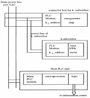
formed the standard EN-50 065-1, in which the frequency bands, signaling levels, and procedures are specified. 3–95 kHz are restricted for use by electricity suppliers, and 95–148.5 kHz are restricted to consumer use. The recorded data in kilowatt-hour meters for every subscriber are sent to host PLC modem via PLC modems, which is placed in subscriber’s locations. On the other hand, energy meter chips are located at the connection points and read the energy in kilowatt-hours and also send the data to host PLC unit. This proposed detector system has two recorded energy data in host PLC unit, one, which comes from the AMR-PLC, and the other, which comes from the PLC modem at the connection points. These two recorded energy data are compared in the host PLC. If there is any difference between two readings, an error signal is generated. This means that there is an illegal
usage in the network. After that, the subscriber address and error signal are combined and sent to the central control unit. If it is requested, a contactor may be included to the system at subscriber locations to turn off the energy automatically, as in the case of illegal usage.

Fig4: illegal detector system of one subscriber

3.1. SIMULATION:
The system model and simulation of the detection system of illegal electricity usage is shown in Fig. 4. It contains a host PLC modem, an energy meter chip and its PLC modem, an electromechanical kilowatt-hour meter and its PLC modem, and an optical reflector sensor system is loaded at the same phase of the power grid. The energy value at the electromechanical kilowatt-hour meter is converted to digital data using by optical reflector sensor. Disk speed of the kilowatt-hour meter is counted and obtained data is sent to PLC modem as energy value of the kilowatt-hour meter. At the system model, an illegal load may be connected to the power line before the kilowatt-hour meter via an S switch. While only a legal load is in the system, two meters are accorded each other to compensate for any error readings. The host PLC unit reads two recorded data coming from metering PLC units. If the S switch is closed, the illegal load is connected to the system, and therefore two recorded energy values are different from each other.
Fig 5: System simulation and modeling of the detection system of illegal electricity usage for electromechanical kilowatt-hour meters

The host PLC unit is generated when it received two different records from the same subscriber. This is the detection of the illegal usage for interested users. In these tests, the carrier frequency is selected at 132 kHz, which is permitted in the CENELEC frequency band. In real applications the AMR systems may be designed in CENELEC bands. The data rate between the host and other PLC modems is 2400 b/s.
Data signaling between PLC modems has a protocol, which includes a header, address, energy value data, error correction bits, and other serial communication bits such as parity and stop bits. The protocol may also be changed according to the properties of the required system and national power grid architecture. Fig.5 shows the detection system for an electromechanical kilowatt-hour meter system. In the digital energy meter system, the recorded energy may be received in the digital form directly using the port of the meter. Therefore, there is no need for an optical reflector system in digital meters. The results of the tests show that this system may solve this problem economically because the budget of the proposed system is approximately U.S. $ 20–25 per subscriber. It is very economical and is a reliable solution when it is compared with the economic loss caused by illegal usage [1].

4. OVER VIEW OF THE PROPOSED DETECTOR SYSTEM:
The proposed detector system is the equipment and procedure for controlling more remote stations from a master control station. It includes PLC modems, energy meters, control logics, and the system software. The PLC modems are host and target modems for two-way communications to and from the host station and the remotely controlled targets. The energy meters include metering chips and some circuit elements; the control and logic units compare and generate the error signal in the
Illegal usage.
The system software has two parts: assembler program for the micro controller and the operating software for the management of the overall system. Operating software may be downloaded from a PC and should be placed in the main center of the system.
An AMR system including an illegal detector performs the following functions.
1) Every user has two PLC modems; one is for AMR and the other is used to send the data from second energy meter chip to host PLC modem.
2) An energy meter must be installed in the connection box between a home line and main power lines.
3) The host PLC unit must be placed in the distribution transformer and the configuration of the addressing format of PLC signaling must be designed carefully.
4) Operating software must be designed for the information of every subscriber in every sub power network: subscriber identification number, billing address, etc……..
5) The system has two values of the energy consumption for every user, so if there is a difference between them, an error signal is generated for the illegal user,
6) The proposed equipment is the only one distributed in the power network. So this system should be repeated for all distribution power networks. All host units in each distribution transformer may be connected to only one main center station via phone lines, fiber-optic cable, or RF links.


Fig 7: Bit-error probability with frequency and load impedance for 1000-m [2]


Results and the variations of the measurements are shown in Figs. 6–7 [2]. The relations between frequency, length, and bit-error probability are given in these figures.. Research work has been taking place in the CPRI, Bangalore for the remote metering and detection of power theft and will soon be helpful to electricity boards in India.

5. CONCLUSION :
The proposed detector system to determine illegal electricity usage via power line communications is examined in the laboratory conditions. Results proved that if AMR and detector system are used together illegal usage of electricity might be detected. Once this proposed detection systems are tried in real power lines, the distribution losses in India can be reduced effectively.

6. REFERENCES :
[1] I. H. Cavdar, “A Solution to Remote Detection of …” IEEE Transactions on power delivery, Vol. 19..
[2] I. H. Cavdar, “Performance analysis of FSK power line communications systems over the time-varying channels: Measurements and modeling,” IEEE Trans. Power Delivery, vol. 19, pp. 111–117, Jan. 2004.
[3] Yoshinori Mizugai and Masahiro Oya “World Trends in Power Line Communications” Mitsubishi Electric
[4] Tom D Tamar kin “Automatic Meter Reading”, Public Power magazine Volume50, Number5 September-October 1992.

Infolinks In Text Ads